Simula 67, the first object-oriented programming language, was created to simplify computer simulations. The following example demonstrates how to simulate a simple device, a stopwatch, with C++ objects. Following the object-oriented approach, software developers model physical entities and intangible concepts by collecting their details in a class. They map the modeled entity's actions to the class's functions, and its data or information to its member variables. Sometimes it isn't clear whether developers should use a variable, a function, or both. Developers can write a correct program in many ways, so they choose the most straightforward way in cases like these.

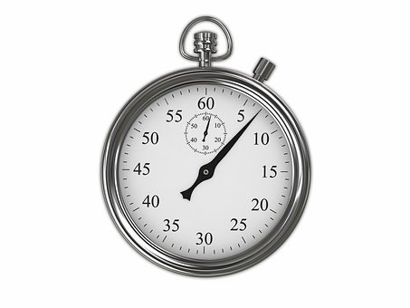
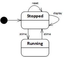
In this example, we will model a stopwatch with two buttons and a display. The display, formed by the two hands and the numbers, displays the elapsed time between starting and stopping the watch. When pressed, the side button resets the display to 0. The top button performs two different operations depending on the watch's state: If stopped, the watch starts; if running, the watch stops. In general, the state of an object is the object's current condition or what the object is doing (e.g., stopped or running).
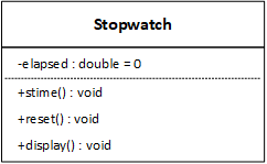
We begin by analyzing the problem. The stopwatch does something or performs some behavior when the user presses either of the buttons. Therefore, it's easy to model the two buttons with functions. In a graphical user interface (GUI) program, the display is always visible, but in a console-based program, we must add a function to display the elapsed time on demand. We implement the display with a variable and a function combination.
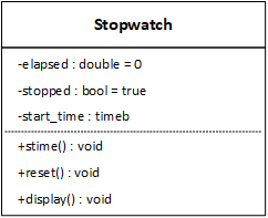
The design phase follows and builds on the analysis. The Stopwatch class currently specifies the three features we identified in the "real world." As we design the program, we discover that it needs two more member variables that analysis didn't identify and are not present in the UML diagram. It's common for a program to require features (variables and functions) beyond those in the "real world." During the design phase, we add these features, called implementation features. We add a variable to store when the Stopwatch object begins running. The time difference between when the watch stops and starts will give us the elapsed time. We also add a flag to represent the watch's state: running or stopped.
 |
 |
| (a) | (b) |
UML class diagrams represent the static structure of an object-oriented program. They specify the data that instances of the class are responsible for maintaining and the operations they can perform. The diagrams form the skeleton or armature of an object-oriented program - every part of the program attaches to and builds on the diagrammed classes. Some classes also exhibit dynamic behavior, meaning that what they do next depends on what they have done in the past. The UML represents dynamic behavior with statechart diagrams based on rigidly specified state machines.
State machines often recognize data patterns or respond to events such as button presses. How we describe some parts of a state machine depends on its purpose. A basic state machine consists of just a few simple parts, each a finite set of elements:

When a program needs a service that doesn't have a language-specific operation, it must use a system call. Such is the case with the stopwatch program, which needs timing information. The program uses a system call that returns the amount of time since the epoch, the computer's beginning of time. On Unix, Linux, and macOS systems, the epoch is January 1, 1970; on Windows systems, it is January 1, 1980. In practice, the program defines a structure with two integer fields: time and millitm. The first field is the number of whole seconds since the epoch, and the second is the number of milliseconds. The program passes the structure by-pointer in the system call, and the operating system fills the structure.
| Structure | System Call | |
|---|---|---|
| Windows | _timeb | _ftime_s |
| Unix Linux macOS |
timeb | ftime |
#include <sys/timeb.h>
The third phase of the software design process is implementation or programming. In a "real-world" situation, it's common for a customer to provide developers with a set of requirements they must adhere to. The absence of formal requirements or a physical watch to model allows the developers to adopt two arbitrary behaviors. First, it may be difficult to reset the time if a mechanical watch is running. So, in that case, we'll choose to do nothing. Second, a mechanical watch continuously displays the elapsed time. We could duplicate that behavior with a GUI program, but not one based on the console. So, we only show the time when the watch is stopped. If a problem specifies a particular behavior, we must follow the requirement; otherwise, we can choose how to implement an operation. If there is a customer, we should get approval (in writing) for our choices.
#include <iostream>
#include <sys/timeb.h>
using namespace std;


class Stopwatch
{
    private:												// (a)
        double      elapsed = 0;
        bool        stopped = true;
        _timeb      start_time;                    // Windows
        //timeb     start_time;                    // Linux / macOS

    public:
        //Stopwatch() : elapsed(0), stopped(true) {}							// (b)

        void reset()											// (c)
        {
            if (stopped)
                elapsed = 0;
        }

        void display()											// (d)
        {
            if (stopped)
                cout << "-------------" << endl << elapsed << endl << "-------------" << endl;
        }

        void stime();											// (e)

    private:
        double    floattime(_timeb t)             // Windows						// (f)
        //double  floattime(timeb t)              // Linux
        {
            return t.time + t.millitm / 1000.0;
        }
};
void Stopwatch::stime()
{
    if (stopped)
    {
        _ftime_s(&start_time);          // Windows
        //ftime(&start_time);           // Linux
        stopped = false;
    }
    else
    {
        _timeb    end_time;              // Windows
        _ftime_s(&end_time);
        //timeb    end_time;             // Linux
        //ftime(&end_time);
        stopped = true;
        elapsed += floattime(end_time) - floattime(start_time);
    }
}
start_time is a temporary value that doesn't characterize a Stopwatch object - it doesn't help describe an object or distinguish between two objects. However, it demonstrates how objects help limit variable scope. Each time the program calls stime, the function uses start_time, implying that the program must save it between function calls. The program can do this without objects by making the variable global or static. Making it global allows any function to modify it inappropriately; making it static prevents the program from simultaneously making multiple stopwatches.
int main()
{
    Stopwatch   sw;							// (a)
    char        op;

    do
    {
        cout << "S\tStart/Stop" << endl;				// (b)
        cout << "D\tDisplay" << endl;
        cout << "R\tReset" << endl;
        cout << "E\tExit" << endl;

        cin >> op;
        cin.ignore();

        switch (op)							// (c)
        {
            case 'S' :
            case 's' :
                sw.stime();
                break;

            case 'D' :
            case 'd' :
                sw.display();
                break;

            case 'R' :
            case 'r' :
                sw.reset();
                break;

            case 'E' :
            case 'e' :
                break;

            default:
                cerr << "Unrecognized operation" << endl;
                break;
        }
    } while (op != 'E' && op != 'e');					// (d)

    return 0;
}
| View | Download | Comments |
|---|---|---|
| stopwatch.cpp | stopwatch.cpp | The Stopwatch program. |